Bug #3400
open
SWD detection fails/SPI Boot failure
Description
The device fails to detect and unable to boot from SPI flash
First observed on 10/2/2026 in TPMS-2W-PCB
Files
 Updated by Thomas Joseph about 2 months ago
@Sumanth D created a ticket with Renesas
Reviewed on 17/03/2026
Action points
- get a simple program - UART or GPIO toggling
- use 1-wire uart, try writing some value to flash and reading back
- isolate flash power and check as https://teams.microsoft.com/l/message/19:fca19e409bf24ac9b45e4b8fa973cd65@thread.v2/1773729368972?context=%7B%22contextType%22%3A%22chat%22%7D
- Read OTP
- probe SPI signals on power-on and see clock and mosi from controller and check when it is stopping
- Document details and update in next PCB version
 Updated by Sumanth D about 2 months ago
- Status changed from Analysis Started to In Progress
- % Done changed from 0 to 30
Please find the design document added with Boot sequence, flow chart, reset and SPI signal wave forms(CLK and MOSI during power on).
Now for step 3 we are doing rework. Once it is done will flash the binary and test
Updated by Sumanth D about 1 month ago
· Edited
Problem
As there is no provision to isolate power to Flash, we cannot able to do as you suggested. As the PCB is too small we couldn't able to cut the tracks also.
Alternatively, we are planning to boot using BOOT step1 from external master.
The Renesas suggested as below
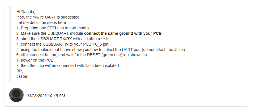
If so, the 1-wire UART is suggested.
Let me detail the steps here:
1, Preparing one FDTI usb to uart module.
2, Make sure the USB2UART module connect the same ground with your PCB
3, short the USB2UART TX/RX with a 1kohm resister.
4, connect the USB2UART rx to your PCB P0_5 pin.
5, using the toolbox that I have show you how-to select the UART port.(do not attach the JLink)
6, click connect button, and wait for the RESET (green one) log shows up.
7, power on the PCB.
8, then the chip will be connected with flash been isolated
Updated by Sumanth D about 1 month ago
- File clipboard-202603231754-bhg97.png clipboard-202603231754-bhg97.png added
- File TPMS_LogFile_20260323.txt TPMS_LogFile_20260323.txt added
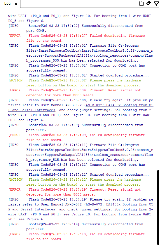
Followed as per the steps suggested by Renesas team.
But we didn't get the RESET(green one) log shows up.
The obtained result is attached and updated to Renesas team and waiting for their reply
Updated by Sumanth D about 1 month ago
- File clipboard-202603261547-thas7.png clipboard-202603261547-thas7.png added
- File Smarttool_log_20260326.txt Smarttool_log_20260326.txt added
- Status changed from In Progress to Resolved
- % Done changed from 30 to 100
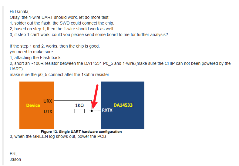
The booting failure issue has been solved. Now the MCU(DA14533) is booting with one wire uart with flash mounted. UART is also working. Log file is attached(terminal log) along with Smart snippets tool log.
Updated by Sumanth D about 1 month ago
- Status changed from Resolved to Feedback